




Solar pump dry run protection should stop or inhibit pumping when the water source cannot safely supply the pump, then permit a controlled restart after recovery. Commissioning must distinguish a genuine low-water condition from weak sunlight, a full storage tank and an unrelated electrical fault. Verify the sensor or approved detection method, the stop response, the alarm and the restart conditions without deliberately damaging the pump. For an LNC133 installation, obtain the exact model and firmware documentation before assigning terminals or parameters; the product family name alone does not confirm a built-in dry-run function.
Separate water availability from solar availability
A solar-powered pump can stop for several legitimate reasons. The source may be depleted, the tank may be full, or the available solar power may be too low for useful operation. These conditions need different operator messages and recovery rules. Treating every interruption as “dry run” makes diagnosis difficult and can encourage unnecessary parameter changes.
Begin with a simple cause-and-effect description. State what detects low water, what detects tank demand, and how the controller decides that solar operation is available. Identify any additional electrical protection. Keep the conditions separate in the alarm history so the operator can tell whether the next action is to wait for water recovery, inspect an instrument or investigate the electrical system.
Define the protection method for this installation
Possible arrangements include a source-level sensor, a pump manufacturer’s integrated sensor, a suitable flow-related device, or a controller’s documented underload function. Each arrangement needs an application-specific assessment. A low electrical load does not automatically prove that a pump is dry, especially when speed and available solar power are changing.
The Water Mission and UNICEF design guide explains the purpose of run-dry sensors and the importance of protecting mechanised pumps when water is unavailable. Use the exact pump and sensor instructions for placement and wiring. This article does not prescribe a universal water-level distance, current threshold or delay for every borehole and pump.
Build a commissioning decision table
| Observed condition | Question to resolve | Acceptance evidence |
|---|---|---|
| Source level below the permitted operating level | Does the intended water-protection input inhibit or stop the pump? | Simulated-input record and correct alarm |
| Tank reaches its demand-off condition | Does filling stop without being labelled a source-water fault? | Tank-control sequence result |
| Irradiance falls | Does the solar operating logic behave as documented? | Controller state and operating trend |
| Sensor connection becomes invalid | Is failure detected or handled by the approved design? | Defined fault-response test |
| Source recovers | Are restart delay, permissives and demand checked? | Recovery sequence record |
| Repeated low-water events occur | Are attempts limited or escalated as specified? | Alarm history and retry behaviour |
These are proposed test scenarios, not factory settings. Fill in the required response and acceptance criteria from the approved design. If the design cannot say what should happen after a lost sensor signal, resolve that omission before using the installation unattended.
Obtain the right documents before touching settings
Collect the pump curve and installation instructions, motor nameplate, inverter manual for the supplied revision, sensor datasheet, terminal drawing and control narrative. Confirm the actual power source arrangement. A solar-only installation and a system that can also receive AC power may have different isolation and control requirements.
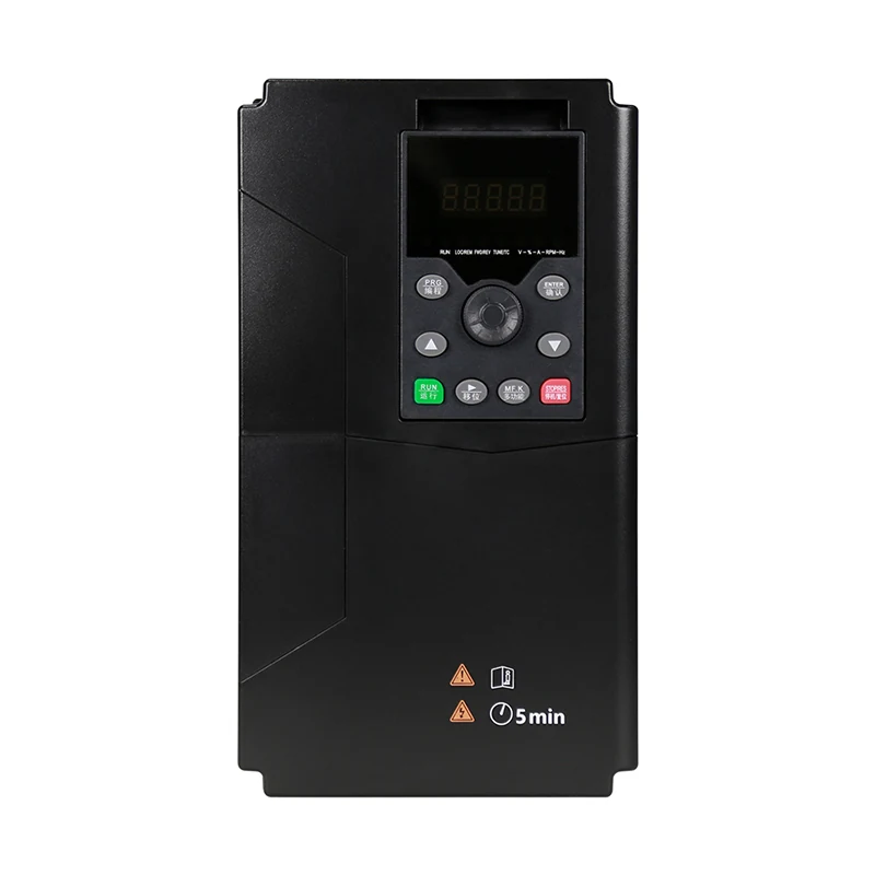
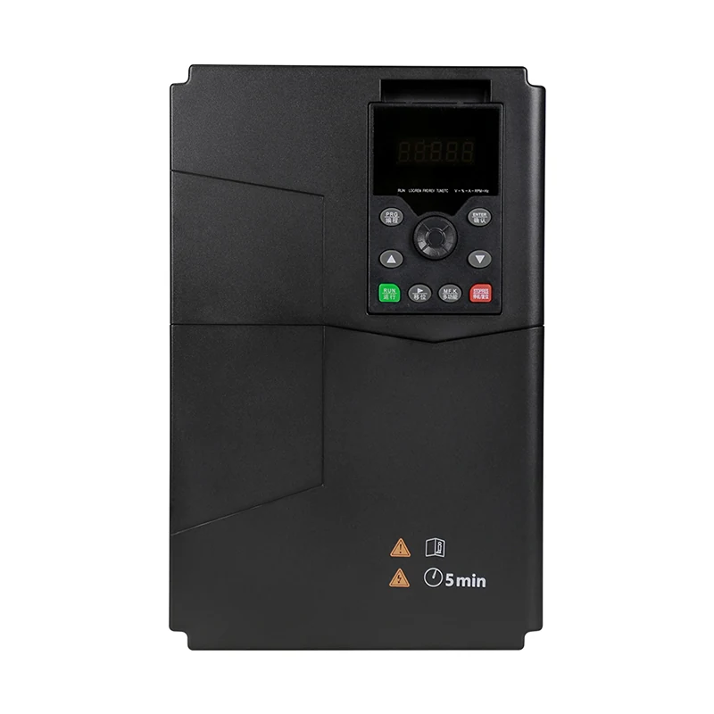
The LNC133 solar water pump inverter page describes the family and solar-pumping application. It should not be read as confirmation of an undocumented dry-run parameter number or input assignment. Ask LINECOME to confirm supported protective inputs or functions for the ordered unit, including what happens after a stop and after power returns.
Establish healthy hydraulic operation first
Before judging a protection threshold, have the pump installer confirm that the system is ready for normal operation. Check the approved water-source condition, priming requirements where applicable, valve positions, discharge route and required submergence. Electrical commissioning cannot compensate for a pump installed outside its hydraulic requirements.
The US Department of Energy pumping-system sourcebook explains why pump behaviour must be considered with the system in which it operates. Use that systems approach when planning observations, rather than treating inverter current as the only useful signal. The pump supplier’s limits remain the reference for the permitted operating region and any restrictions during testing.
Record a usable baseline
During a safe wet run, record the operating state, available measurements and the conditions under which they were taken. Useful entries can include motor current, output frequency, source-water condition, delivered flow, pressure and solar availability, where suitable instruments exist. Note whether values are measured, controller-reported or estimated.
One healthy reading is not a complete operating envelope. If an electrical underload method is proposed, the supplier must explain how it distinguishes water loss from normal changes in operating speed and available energy. Do not take a single midday current reading, subtract an arbitrary percentage and present the result as an approved dry-run threshold for every season.
Test low-water response by approved simulation
Use a documented sensor test facility or an agreed simulation at the designated control point. Keep the pump in a safe hydraulic condition. Verify that the controller recognizes the low-water state, commands the specified stop or inhibit, and presents the right alarm. Retain the test conditions and observed response.
Avoid running the pump dry simply to see whether protection eventually operates. A destructive test can damage equipment before a threshold is proven. If a supplier requires a particular commissioning method, obtain the written procedure and have the responsible engineer assess it. Where a function cannot be validated safely at the factory, define the site test and its prerequisites instead of marking it passed.
Check sensor failure as a different condition
A source-level sensor can fail, a cable can be damaged, and a terminal can become disconnected. Ask what the chosen input circuit can diagnose and what the controller should do when a signal is invalid. “Normally closed” or “normally open” is only part of that description; the complete sensing circuit matters.
Test only the failure simulations permitted by the design. Confirm whether the resulting message identifies a sensor problem or simply indicates that pumping is unavailable. An alarm that claims certainty beyond the installed sensing capability can mislead maintenance staff. Record any diagnostic limitation in the operating instructions so the team knows what to inspect before resetting the system.
Treat restart as a separate acceptance test
After a simulated low-water condition, restore the input according to the approved procedure. Verify that the controller checks water availability, tank demand and any other permissives before restarting. Confirm whether a delay, manual acknowledgement or limited retry sequence is required. There is no single restart delay suitable for every water source.
Water recovery depends on the source and operating conditions; it should be considered by the water-system designer. Repeated rapid attempts can hide an inadequate source or an incorrect setting. Ask the operator to demonstrate how a persistent problem is escalated. A controller that restarts once under workshop simulation has not necessarily proven unattended operation through repeated source depletion.
Distinguish tank demand from source protection
A full tank should normally produce the stop or inhibit defined by the filling strategy. It should not be confused with a depleted source. Test the tank input separately and confirm what happens when water is again required. If both conditions exist together, agree which information appears and which conditions must clear before pumping can resume.
Where multiple floats or level thresholds are used, label them consistently on drawings and screens. Verify the physical device identity during site acceptance. The correct software response to a simulated signal does not establish that the real float was fitted at the intended level or connected to the intended terminal. That field check needs its own record.
Control electrical and stored-energy hazards
Solar modules can continue to provide electrical energy in daylight. Additional supplies, remote commands and stored energy may also be present. Have qualified personnel identify every energy source and follow the approved isolation, discharge and verification procedures before servicing. A stopped pump or dark display is not sufficient evidence of an electrically safe condition.
NIOSH hazardous-energy guidance supports a planned approach to preventing unexpected energization. For this installation, document the inverter and PV-specific requirements from their manufacturers. Keep functional tests separate from maintenance isolation, and make sure that a remote demand signal cannot unexpectedly restart equipment while a person is working on it.
Handover the logic, settings and remaining site checks
Create a final record showing the confirmed protective method, sensor reference, terminal assignment, settings revision, tested scenarios and unresolved items. Include a simple operator explanation of low source water, full tank, insufficient solar availability and electrical fault states. Preserve the previous settings whenever a controlled adjustment is made.
For related control behaviour, consult the site’s pump PID and drive-fault articles, together with its broader drive operating-principle guide. They address adjacent questions rather than replacing this water-availability test. When requesting an LNC133 solution, provide the motor data, source characteristics, required daily water delivery, tank-control arrangement, available instruments and desired restart policy so the supplier can assess the complete application.
Educational video: understand the pump before the controls
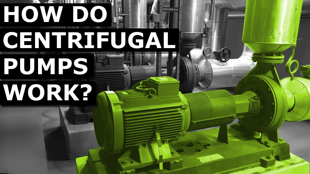
Video: The Engineering Mindset. Watch How do centrifugal pumps work? on YouTube.
The Engineering Mindset explains centrifugal-pump operation in this neutral educational video. It helps connect motor operation to the hydraulic system. It does not demonstrate LNC133 dry-run settings or establish which protection method is fitted to a particular installation.
Related LINECOME guides
- How a Variable Frequency Drive Works — From Line Power to Motor Speed
- VFD PID Control for Constant-Pressure Pumps: Setup and Tuning
- VFD Overvoltage Fault Troubleshooting: A Practical Diagnostic Guide
Frequently asked questions
Is low current always a sign of dry running?
No. Current can change with speed, solar availability and hydraulic conditions. Use only a documented detection method that has been assessed for the actual pump and operating range.
Should the pump be run dry to prove protection works?
Do not improvise that test. Use an approved simulation or manufacturer-defined procedure that protects the pump and personnel, and record what part of the protection chain was demonstrated.
Does every LNC133 have the same dry-run parameters?
Do not assume so. Confirm the supplied model, firmware, supported inputs and protective functions with the exact documentation before assigning a terminal or entering settings.


