




A PLC 24V DC voltage drop investigation should compare voltage at the power-supply output with voltage at the affected load during the same operating event. A healthy reading beside the supply does not establish adequate voltage at a remote I/O station, sensor or controller. Start with the circuit drawings, the exact device operating limits and a recorded symptom. Then separate source collapse, distribution loss and a shared return problem. This keeps the investigation connected to what the equipment actually experiences when a valve energizes, a communication module starts or a machine restarts.
Define the affected circuit before measuring
Write down which device loses function and what the controller records. A CPU restart, a remote I/O communication interruption and one unstable transmitter need different initial boundaries. The CPU can remain operational while an independently supplied field device loses power. Likewise, a process value can change because its transmitter resets, even though the input module itself remains healthy.
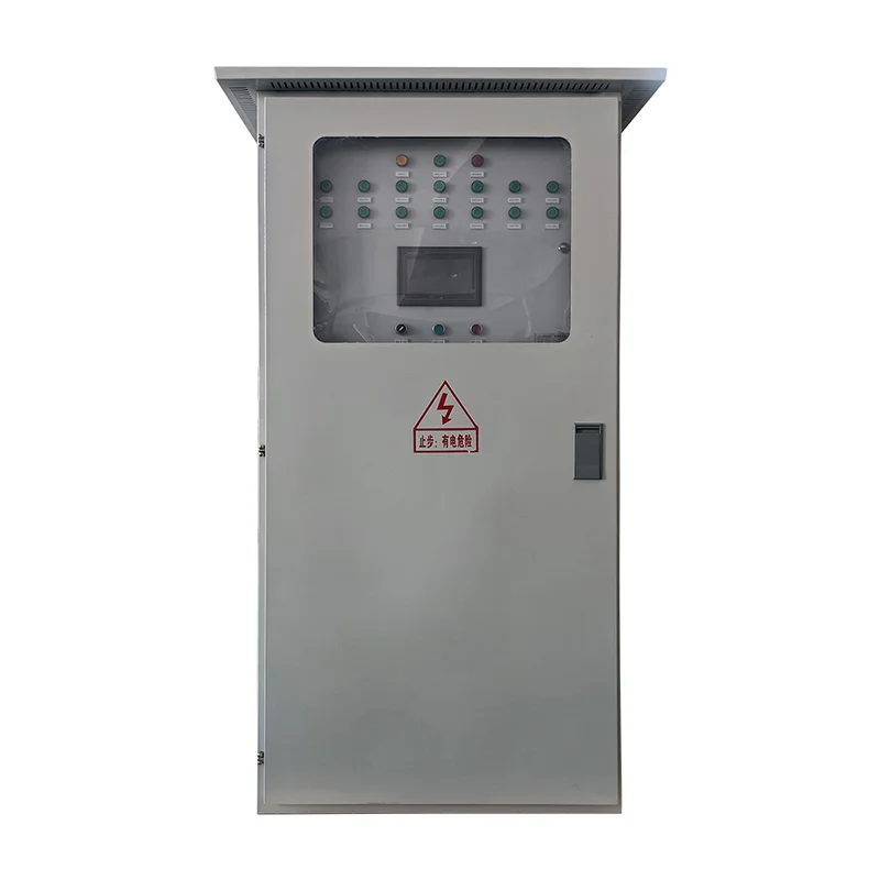
Use the PLC cabinet overview to identify the main equipment groups, then trace the particular positive feed and return on the approved drawing. Include terminals, connectors, branch protectors, distribution modules and any redundant-supply interface. Record equipment references rather than relying on wire color or physical proximity. Two terminals marked 24 V may belong to different supplies or protected branches.
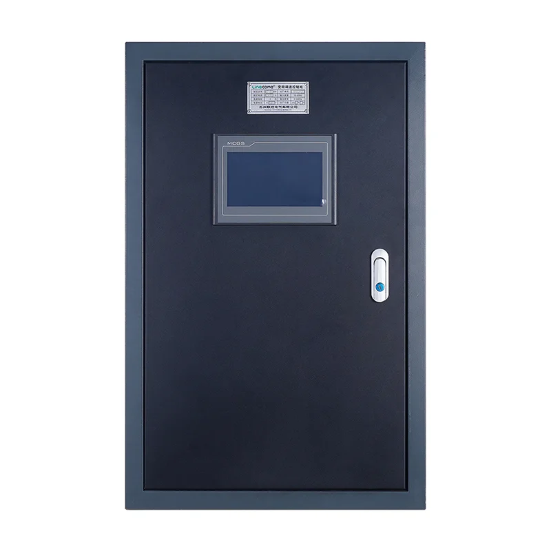
For a cabinet project, the industrial PLC control cabinet provides a relevant construction reference. Its photograph identifies a product arrangement, while the order drawings determine the installed power supply, branch circuit and field wiring. Do not infer a particular supply rating or redundancy arrangement from the enclosure appearance.
Establish a safe and useful measurement plan
Electrical measurements inside a cabinet require competent personnel and the site’s authorized work procedure. A control circuit can be near hazardous power circuits, and machine movement can occur when power returns. The HSE maintenance guidance explains the importance of planning, isolation and managing stored energy during maintenance. Decide the safe machine state and authorized test conditions before connecting instruments.
Identify accessible measuring points on the drawings. Specify the instrument, its suitable voltage and environment ratings, and the time resolution required to capture the symptom. A handheld meter may establish steady voltage but miss a short interruption. A suitable recorder can show whether the fault coincides with a transient. Connect and use it under the approved procedure, including the required precautions for its measurement reference.
Do not begin by opening field branches at random on an operating machine. Removing a sensor or output supply can change control behavior. Agree which loads can be separated, how the process will be secured and which person controls restart permission.
Compare source and load under representative demand
First establish a baseline with the affected equipment connected. Record the voltage directly across the supply output and directly across the device power terminals. At the load, use its own positive and return terminals. A reading to protective earth answers a different question from the voltage available across the device supply input.
Next reproduce an authorized operating event that normally accompanies the symptom. Record the event time, active loads, source voltage and load voltage. Where the event is brief, synchronized recordings are more informative than unrelated measurements taken minutes apart. Confirm that each measurement uses the correct circuit reference and record the minimum captured value together with the recording duration.
If source and load both fall together, investigate upstream supply conditions, power-supply loading and its protection response. If the source remains steady while the load falls, investigate the distribution path. If only one group is affected, examine the shared positive feed, return and protection interface for that group before assuming a cabinet-wide problem.
The following table is a proposed diagnostic organizer. It assigns the next evidence to collect, rather than a universal pass voltage. Acceptance limits come from the exact connected devices and the project design.
| Observation during the event | Next comparison | Evidence needed before correction |
|---|---|---|
| Supply output and several loads fall together | Supply input, output current and protection indication | Input event record, connected-load schedule and supply behavior |
| Supply output stays steady but one distant load falls | Positive and return distribution paths | Loaded terminal readings and the exact branch drawing |
| Several devices on one branch restart | Shared protector, connectors and return junction | Branch current and time-correlated voltage records |
| CPU remains running while remote I/O disappears | Remote station supply and communication diagnostics | Local supply event and network event timestamps |
| Only the process value fluctuates | Transmitter supply and analog channel behavior | Power stability plus separate signal investigation |
Separate distribution resistance from source limitations
For a simple DC circuit, the steady resistive voltage loss is ΔV = I × R, where ΔV is volts, I is amperes and R is the total series resistance in ohms. Include the outgoing conductor, return conductor and relevant connections. Device-specific voltage drops, such as a distribution interface, must be considered separately where they are not represented by that resistance.
For an illustrative calculation, assume a source measured at 24.0 V, a 2.0 A load and a measured or calculated total series resistance of 0.80 Ω. The resistive loss is 2.0 × 0.80 = 1.60 V, leaving approximately 22.4 V at the load before other losses. These assumed numbers demonstrate the calculation. They do not establish an acceptable PLC voltage or a recommended cable size.
Repeat the estimate for the relevant operating current and conductor temperature assumptions. A calculation made with an idle current cannot explain a loaded event by itself. Conversely, an assumed resistance should be checked against the installed route, conductor data and connection condition. The result becomes useful when it predicts a measurable difference between source and load.
If the measured difference is concentrated across one connector or terminal interface, plan an isolated inspection and repair. Use the specified preparation and tightening instructions. Replacing a sound power supply will not remove resistance in a damaged distribution connection.
Check the whole load schedule and startup sequence
List controller, I/O, HMI, network, instrumentation and output loads supplied by each DC source. Separate normal demand from simultaneous startup and intermittent demand. Identify loads that are supplied externally and those supplied through a controller or module. This avoids adding the same load twice or overlooking a field branch.
Texas Instruments’ PLC input-protection reference design describes an architecture with external DC power, input protection and backup supply functions. It illustrates why undervoltage, overload and protection behavior belong in a PLC power review. Its component-level implementation is a reference design, so its ratings are not acceptance limits for an assembled LINECOME cabinet.
Check the installed supply documentation for its continuous rating, temperature restrictions, current-limiting behavior and supported transient demand. Compare those conditions with the measured installation. A supply operating in a protective mode may show a different pattern from a simple distribution loss. Record its indicators and available diagnostics while the symptom occurs.
A change in startup sequence can reduce simultaneous demand in some systems, but it also changes machine behavior. Review the control dependencies and abnormal states before applying it. Capture the resulting sequence in the drawings and test record so maintenance staff can reproduce the intended operation.
Keep the return path in the investigation
A good positive feed cannot compensate for a poor return connection. Follow the return conductor through field connectors, terminal groups and distribution points. Where several loads share a return segment, their combined current can affect the voltage available to each device. Compare the affected branch with an unaffected branch that genuinely shares the same source.
Do not treat a measurement between return and protective earth as permission to add a bond. The required earthing arrangement depends on the designed supply system, equipment instructions and fault-detection approach. Document the existing arrangement and have the responsible designer assess any change. An improvised connection can alter fault paths and create new problems.
Once device power is shown to remain within its specified conditions during the symptom, move to the appropriate signal or network investigation. The PLC analog input noise guide covers receiving-channel and signal-path questions. Keeping the voltage record alongside that investigation makes it easier to establish whether the changing reading came from the supply or from the measurement circuit.
Select corrections against the measured cause
Possible corrections include repairing a connection, changing an appropriately engineered conductor route, redistributing loads, revising a branch-protection arrangement or selecting a suitable supply. Each addresses a different failure mechanism. Compare the expected effect with the original readings before approving the change.
RealPars’ explanation of 24VDC supply problems discusses ripple, overload and distribution issues as separate contributors to unreliable operation. Use that separation when describing the fault. A stable average voltage with excessive disturbance needs different evidence from a long conductor producing a steady loaded drop.
Raising the supply setting needs an explicit review of every connected device’s permitted input range, including devices near the supply. A setting that helps a distant branch may expose a nearby device to excessive voltage. Added capacitance or backup power also requires review of inrush, protection and restart behavior. Record the intended mechanism of the correction and its applicable limits.
Prove recovery and leave a repeatable record
Repeat the original operating event after the correction using the same measurement points and a comparable load condition. Compare source and load records, device diagnostics and process behavior. Include the most demanding authorized startup combination that the project requires, rather than accepting an unloaded power-on result.
Use the PLC cabinet FAT checklist to place the result in the broader cabinet handover. Attach the circuit revision, instrument record, load schedule, before-and-after readings and final settings. If field cables were represented by temporary workshop wiring, identify the remaining site test explicitly. The installer should know which conclusion depends on the final cable route.
Further learning about PLC power supplies
The following RealPars lesson explains the role of a PLC power supply and its relationship to the rest of the hardware. It supports component identification before tracing the specific circuit. For actual fault measurements, follow the installed equipment documentation and the authorized site procedure.
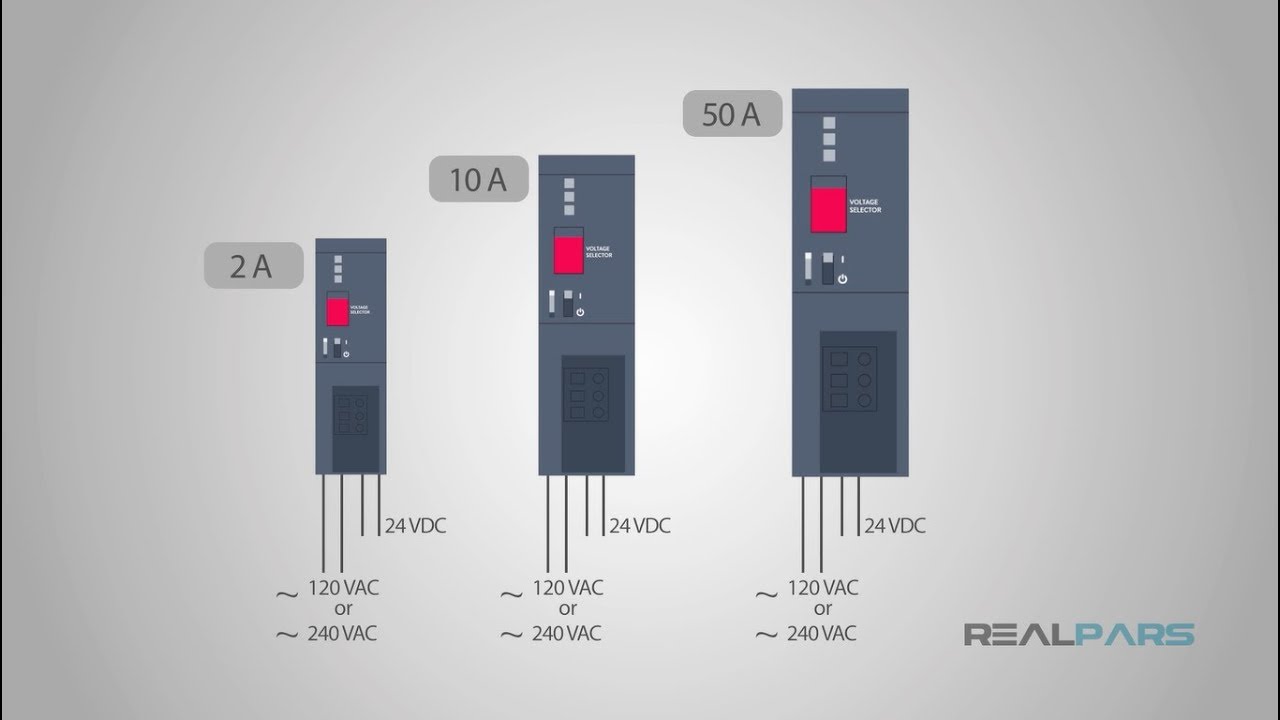
Video by RealPars. Watch How PLC Power Supplies Work on YouTube.
Frequently asked questions
Is 24 V at the supply enough to clear the power circuit?
Measure at the affected device during the relevant operating event as well. Distribution loss, return connections and short interruptions can leave the load with different conditions from those measured at the source.
Can a larger power supply fix every voltage drop?
A larger supply may help when its capacity or supported transient demand is the demonstrated limitation. It will not repair a resistive connection or an incorrectly arranged return path. Select the correction using the recorded cause.
What voltage should trigger a failure verdict?
Use the operating range and interruption tolerance of the exact connected device under the specified conditions. Record the minimum voltage and event duration, then compare both with the applicable documentation and project acceptance criteria.


