




Circuit breaker auxiliary contact vs alarm contact is a distinction between the breaker’s indicated position and a specified trip event. A position contact can change when the breaker is opened manually or by a trip. An alarm contact responds to the events defined for that accessory, which may exclude some opening causes. Before ordering or connecting either one to a PLC, obtain the exact accessory diagram and build a state matrix. Neither signal alone proves electrical isolation, identifies every fault cause, or confirms that voltage is absent downstream.
Start with the information the operator actually needs
Write the required messages before choosing an accessory. “Breaker open,” “protection trip,” “remote opening command active,” and “control supply unavailable” describe different conditions. A single input named “breaker fault” cannot reliably communicate all four. Ambiguous labels encourage unnecessary resets and make the maintenance history less useful.
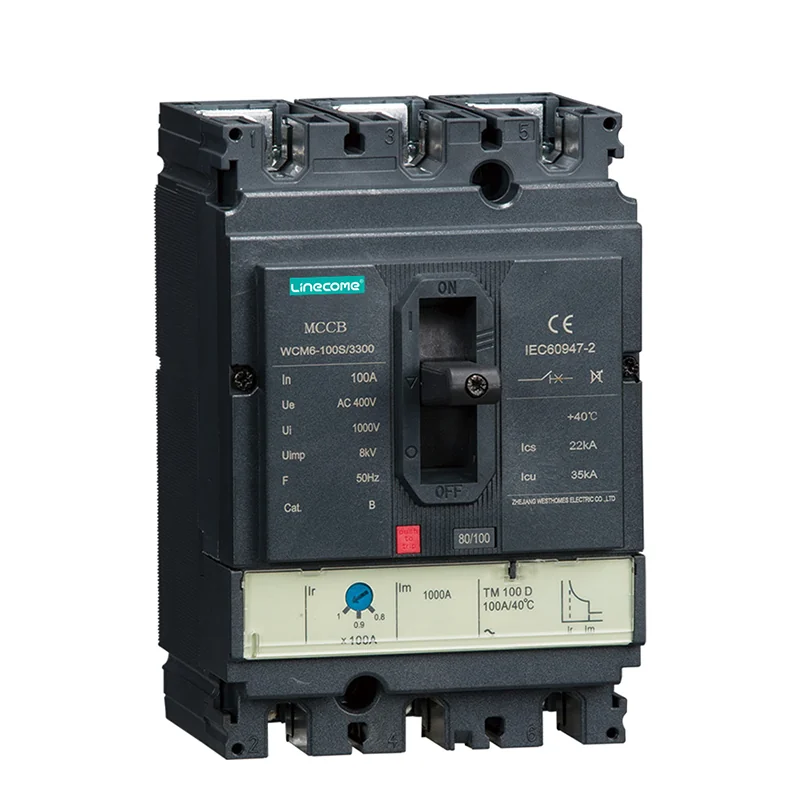
For a WCM8 moulded case circuit breaker, request the available indication accessories for the exact frame and supplied version. Confirm the accessory identity, mounting compatibility and supported functions. The product family description and exterior photograph do not establish that a particular contact block is fitted or define what causes its contacts to operate.
Ask whether the signal is informational, a process permissive, or part of a separately designed safety function. That decision affects the evidence and design review required. An ordinary status accessory must not be promoted into a safety-rated monitoring device simply because the controller can display its state.
Distinguish a position contact from a trip indication
An auxiliary position switch reports a state associated with the breaker mechanism or contacts as defined by its manufacturer. Opening the breaker by hand can therefore produce the same position indication as opening after a protective trip. Position feedback answers whether the indicated open or closed state is present; it does not automatically answer why the breaker changed state.
A trip or alarm switch has a more specific operating definition. Some accessories indicate a tripped mechanism, while an overcurrent trip switch can be limited to operation of the protection unit. Shunt release operation, undervoltage release operation and manual opening must each be checked against the accessory instructions. Avoid assuming that every item called “alarm contact” responds identically.
The RealPars circuit breaker explanation introduces the distinction between ordinary circuit operation and protective interruption. It provides background rather than a terminal diagram or an accessory state table. The installed accessory documentation remains the authority for the actual signal behavior.
Create a state matrix before writing the PLC description
The following is an original review checklist. Its entries are questions to resolve from the supplied documentation and approved tests, not universal contact states. Enter actual terminal numbers and observed results in the project copy. Record unavailable functions explicitly instead of treating a missing accessory as a healthy signal.
| Condition to review | Position indication question | Alarm indication question |
|---|---|---|
| Breaker closed normally | Which contact state represents closed? | What is the normal reset state? |
| Manual opening | Does the position contact follow opening? | Does this accessory remain normal? |
| Protection trip | Which position and trip indications change? | Which protective events are included? |
| Shunt release opening | What indicates the resulting position? | Is remote release included or excluded? |
| Undervoltage release operation | What happens as control power disappears? | Can the indication still be read? |
| Trip reset without reclosing | Does the breaker remain indicated open? | When does the alarm contact reset? |
| Broken signal conductor | Can the controller distinguish an input loss? | What diagnostic response is specified? |
| Loss of PLC input supply | Which indications become unavailable? | Is unavailable distinguished from normal? |
Use the matrix to agree the HMI wording with the owner. “Open, cause unconfirmed” can be more accurate than “overload” when only a position input exists. Keep the matrix with the approved schematic so later replacements do not silently change the meaning of a signal.
Read normally open and normally closed in the documented reference state
NO and NC describe contacts relative to a stated normal condition. Determine what the manufacturer means by that reference condition for the accessory. A breaker diagram may distinguish open, closed, tripped and reset mechanism positions. Do not infer terminal behavior from the position in which the equipment happened to arrive.
For a changeover contact, identify the common terminal and both switched terminals from the actual diagram. Record the expected continuity for the relevant breaker states. A wire color or a remembered numbering convention can support identification, but it cannot replace the supplied marking and schematic.
Keep the electrical contact state separate from the PLC variable. A closed contact can produce a true input in one circuit and a different interpreted result in another. Document the complete path from accessory terminal to input channel, logic interpretation and displayed message. This avoids an inverted alarm after an otherwise correct hardware replacement.
Match the contact rating to the signal circuit
Check the accessory’s rating for the actual voltage, AC or DC duty, current and load type. A power contact rating does not automatically establish dependable behavior with a very small PLC input current. Ask for the applicable minimum switching conditions where provided and the correct accessory for electronic inputs.
Also check the input module type and reference connection. A dry contact does not create its own sensing supply. The circuit must provide the correct source and return path without connecting incompatible supplies. Review channel isolation and common terminals before joining signals from different panels.
For the controller side, the site’s PLC sinking and sourcing input guide explains a related compatibility question. Use it to review the input arrangement, while retaining the breaker accessory’s own ratings as a separate check. Neither a higher rated breaker nor a larger power cable corrects an incompatible indication circuit.
Keep commands, positions and causes as separate records
A PLC opening command records an intention. An auxiliary input records an observed indication. A protection event record reports a detected condition. These records can support one another, but one must not be silently substituted for the others. A command bit that turns on does not prove that the mechanism moved.
Where the approved design compares command and position, define the allowed transition and response to a mismatch. The responsible engineer should set timing from the actual equipment and process requirements. This guide does not provide a generic delay that would suit every breaker, communication system or safety function.
A trip indication also should not automatically name the failed component. A protective operation can result from a genuine downstream fault, an incorrect setting or another documented condition. Preserve the first event and investigate it using the applicable procedure rather than treating an alarm reset as a repair.
Verify the complete chain with an approved test plan
Begin with a safe work arrangement and documented test boundaries. Confirm which supplies and stored energy sources remain present. Testing indication contacts is different from proving a safe condition for work on the power circuit. Follow the site procedure and the CCOHS lockout guidance for the general hazardous-energy-control principles.
Qualified personnel should use the manufacturer’s permitted operating and testing methods. Do not create a live short circuit, defeat a protective interlock or deliberately introduce an uncontrolled undervoltage merely to see an alarm. A test button or simulation must be used only for the functions its instructions actually cover.
Observe the accessory, field terminals, PLC input and HMI together. Record both the electrical state and the message shown. If testing only simulates an input at the PLC, label it a logic test; it does not prove the accessory, field wiring or mechanical linkage. Keep simulated and end-to-end evidence separate in the report.
Include reset behavior and loss of signal in acceptance
After an approved trip test, observe the sequence through reset and, if authorized, reclosure. An alarm can clear before the breaker closes, or it can remain latched in the HMI after the accessory returns to normal. Both arrangements need an explicit explanation so the next operator knows what has been acknowledged and what is still open.
Review what happens when an indication circuit loses power. A disappearing input may mean open contacts, a broken conductor, a blown control fuse or an unavailable input supply. The installed circuit may not distinguish these automatically. State that limitation instead of describing every zero input as proof of one mechanical condition.
Do not add automatic reclosing just to make alarm recovery convenient. Restoring the breaker and restarting the connected machine are separate decisions governed by the process and approved controls. Record which action requires local inspection, manual authorization or a separate restart command.
Make the replacement and handover package unambiguous
For purchasing, provide the breaker model, frame, accessory part reference, required functions, contact arrangement, electrical duty and mounting details. Include the required terminal drawing and label language. A request for “one auxiliary contact” leaves too many opportunities for a correct-looking but functionally different delivery.
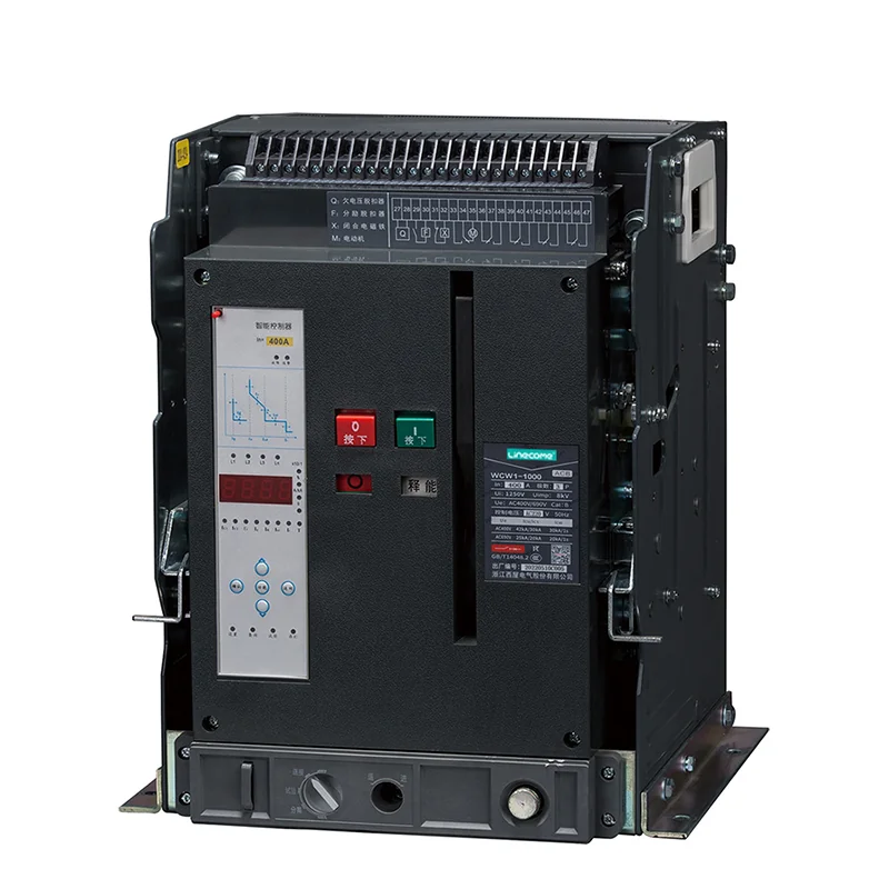
For handover, attach the final state matrix, circuit drawing, PLC input list, HMI messages and completed test record. Identify any indication that was not tested and why. The air circuit breaker mechanical operation guide covers a related operating-chain review; it is not a substitute for the accessory-specific tests described here.
Use the site’s circuit breaker product overview to identify the relevant equipment category, then obtain the exact supplied documentation. If the required indication is unavailable, revise the monitored function transparently rather than renaming an ordinary position contact as a protection alarm.
Educational video: understand protective interruption
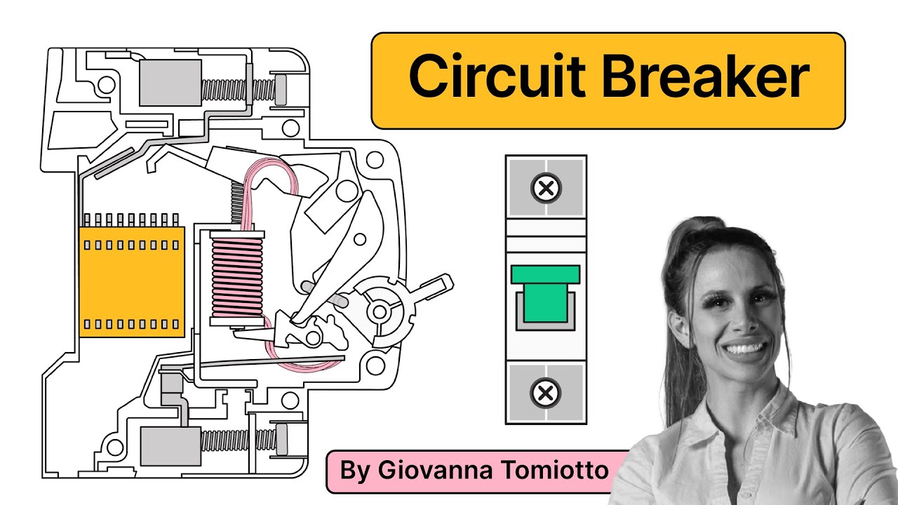
Video by RealPars. Watch Circuit Breaker Explained | Working Principle on YouTube.
RealPars explains basic breaker operation. Watch it as background for separating an opening event from ordinary load operation. It does not define WCM8 accessory terminals, alarm coverage or safety performance.
Frequently asked questions
Does an open-position input prove that the breaker tripped on overload?
No. Manual opening and other release operations can produce an open indication. Confirm the specific trip accessory and event record before assigning a cause.
Can any alarm contact replace an auxiliary position contact?
No. Their operating definitions, reset behavior and electrical ratings can differ. Check the exact accessory diagram and project state matrix before replacement.
Is a breaker position contact enough to prove safe isolation?
No. A status indication is not verification that all hazardous energy is controlled. Apply the site isolation procedure and the equipment-specific requirements.


