




VFD overvoltage fault troubleshooting starts by identifying when the fault occurs: before the motor runs, during steady operation, during deceleration, or while the load drives the motor. Those conditions point toward different causes. A high incoming supply, a transient event, regenerated mechanical energy, unsuitable braking equipment or an internal sensing problem can all require investigation. Do not assume every overvoltage trip needs a braking resistor, and do not increase a protective threshold simply to keep production running. Preserve the fault record and compare the event with the exact drive manual before changing anything.
This guide focuses on diagnosis and evidence collection. Our VFD operating-principle guide explains the power stages. The separate braking resistor sizing article covers component calculations, while the acceleration and deceleration guide explains ramp selection. Use those pages after the fault evidence identifies which part of the system needs attention.
Understand what the fault code is monitoring
Many drives report overvoltage when the monitored DC-link voltage exceeds a protective limit. The alarm name does not necessarily mean that motor-terminal voltage was measured above its rating. A drive includes a rectifier, a DC link and an inverter, and the location of the monitored quantity matters. Check whether the code specifically refers to the DC bus, input voltage or another circuit.
Thresholds, detection delays and fault-history fields differ by voltage class and model. Record the full equipment identification, firmware where available, exact code and manual revision. A number found in a forum for another drive is not a valid threshold for the installed unit. Confirm the meaning of any displayed voltage before interpreting it as line-to-line AC or DC-link voltage.
Save the evidence before a reset removes the context
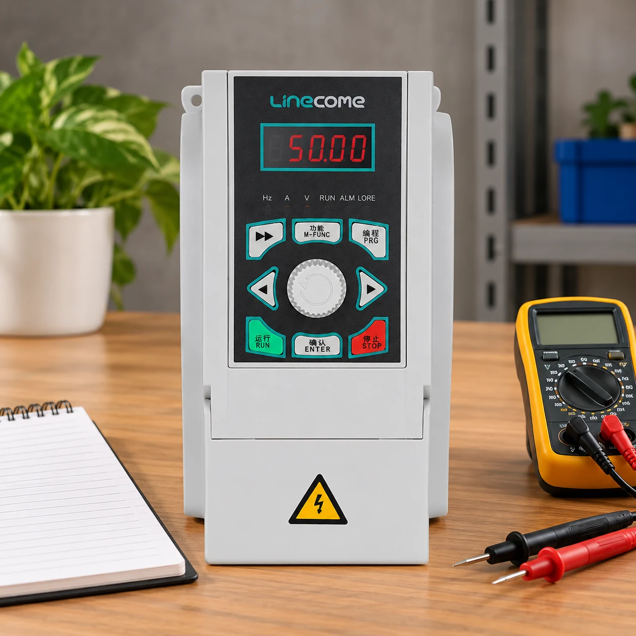
Record the time of the event, operating mode, speed command, actual output frequency, load condition and whether the machine was accelerating or slowing. Preserve available current and bus-voltage history. Note recent maintenance, changed production cycles, utility events and parameter adjustments. A photograph of the alarm display is useful, but a record showing what happened immediately before it is usually more informative.
Stop repeated reset attempts if the cause is unknown or the machine cannot restart safely. An automatic restart can create a mechanical hazard even when the electrical fault disappears. Investigate within the site’s isolation and commissioning procedures. Removing incoming power does not prove the DC link has discharged; follow the manufacturer’s waiting, verification and stored-energy instructions with qualified personnel.
The physical reason for this caution is explained by OpenStax’s capacitor-energy discussion: stored energy depends on capacitance and the square of voltage. This principle does not establish the discharge time of any particular drive. Do not open the enclosure or probe the DC bus based on a generic waiting period from an article.
Use the event timing to choose the first investigation
| When the fault appears | First questions | Evidence to collect |
|---|---|---|
| Power applied, motor stopped | Is supply voltage appropriate for the exact model? Was there a supply event? | Equipment rating, approved supply measurements and fault history |
| During deceleration | Is the load returning energy faster than the drive can absorb it? | Actual stop time, load, bus trend and braking configuration |
| During lowering or back-driving | Does the process drive the motor continuously? | Motion sequence, load direction and duration of overhauling duty |
| Steady-speed production | Is there a sudden load change, supply disturbance or another energy source? | Time-correlated process and supply records |
| Intermittent, unrelated to load | Is the supply unstable or does the measurement need service investigation? | Repeatable event records and qualified diagnostic results |
This table organizes the investigation; it does not assign a diagnosis from timing alone. A supply disturbance and regenerated energy can occur together. Check the evidence against the equipment documentation before selecting a repair or changing the operating sequence.
If the fault occurs at power-up, check the supply boundary
Verify the drive’s rated input voltage and the actual supply arrangement. A transformer connection, tap setting or replacement drive with the wrong voltage class can create a mismatch. Establish whether measurements were taken at the relevant location and under the relevant condition. A reading from a nearby panel on another circuit may not describe the drive’s incoming supply.
Where intermittent supply events are suspected, qualified personnel may need suitable recording equipment rather than a single handheld reading. Correlate timestamps with other equipment and utility records. Do not infer a transient from an unexplained fault alone, and do not add line reactors, surge devices or other equipment without checking the installation and the drive supplier’s recommendations.
Some drive architectures can return energy to a common DC link or interact with other connected equipment. Identify that architecture explicitly. A standalone diode-input drive, a common-bus system and an active regenerative supply do not have the same energy paths. Changes made for one arrangement can be inappropriate for another.
If it trips on deceleration, investigate returned energy
A rotating load can continue driving the motor while the drive commands lower speed. That energy may raise DC-link voltage if there is no suitable path to dissipate or recover it. The likelihood depends on inertia, speed change, stopping time, mechanical losses and the load torque. Motor rated power alone cannot describe the complete braking event.
For an illustrative rotating system with inertia J = 1 kg·m² slowing from 1,500 rpm to rest, angular speed is approximately 157.08 rad/s and the kinetic-energy change is approximately 12.34 kJ. Releasing that energy over two seconds represents about 6.17 kW of average mechanical braking power; over ten seconds it represents about 1.23 kW. These simplified calculations ignore losses and external load torque.
The example shows why a longer stop can reduce power demand, but it does not select a resistor or establish a safe stop time. Peak power differs from average power, and a production process may require a specific stopping performance. The underlying energy relationship is covered in OpenStax’s rotational kinetic-energy chapter. Use actual inertia and motion data for engineering decisions.
Separate a diagnostic ramp test from a permanent correction
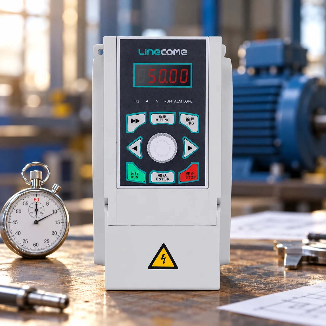
If the equipment owner and commissioning procedure permit it, a longer deceleration setting can help determine whether braking demand contributes to the fault. Record both the requested ramp and actual stopping time. A drive may already be extending the ramp through an overvoltage-control function, so an entered parameter does not necessarily describe the observed stop.
A fault disappearing during one longer stop is evidence, not a complete acceptance test. Repeat the evaluation at the intended load and duty within approved limits. Confirm mechanical stopping requirements, process response and repeated-cycle heating. A correction that avoids the drive alarm but produces an unacceptable stopping distance is not an acceptable machine solution.
Check braking hardware only against the exact configuration
Identify whether the installed drive has a braking chopper, whether a separate brake unit is required and whether the selected resistor is approved for that arrangement. Check the permitted resistance and braking duty from the supplier’s documentation. An available terminal label does not prove that every unit in the family contains identical braking hardware.
A resistor with the wrong resistance can be unsuitable even if its wattage appears generous. A resistor with acceptable resistance may still lack pulse-energy or repeated thermal capacity. Wiring, thermal protection and installation clearances also belong in the review. Inspection of internal circuits should follow the applicable isolation and stored-energy procedures; this guide does not provide live test instructions.
For hoists and other overhauling loads, include steady lowering or back-driving time. A calculation that considers only the final stop can miss most of the returned energy. Mechanical holding and power-loss behavior require their own design review. A resistor that absorbs energy during motion does not provide a mechanical holding brake.
Consider sensing or internal faults after external evidence is reviewed
If the reported bus value conflicts with qualified measurements or the event cannot be explained by the supply and load, involve the drive supplier or an authorized service provider. Preserve the original event history and configuration. Do not conclude that the drive is defective merely because a longer ramp did not help; the supply and operating sequence may still require more evidence.
Describe what has actually been ruled out and how. “Supply checked” should identify the measurement location, operating condition and method. “Braking resistor checked” should identify the resistance, documented compatibility and inspection performed. Clear records reduce repeated troubleshooting and prevent an intermittent problem from being dismissed after a short successful run.
Define an acceptance test and handover record
Validate the corrected configuration through representative starts, stops, operating speeds and load directions. Include the shortest intended repeating cycle and the most demanding permitted stop. Confirm that no protective threshold was raised beyond approved settings and that thermal protection, alarms and restart behavior remain appropriate.
Record the final parameters, installed braking components, tested load, actual stopping times and any operating restrictions. If production later changes the load or cycle frequency, review the acceptance assumptions. A previous successful test does not automatically cover a heavier load, a faster stop or a warmer enclosure.
What to send with a LINECOME support enquiry
Provide the exact drive model, supply information, motor nameplate, fault code, event timing, available voltage/current traces, ramp settings and braking-unit details. Include recent changes and a concise description of the driven equipment. Ask for model-specific guidance rather than a generic voltage threshold or resistor recommendation.
The LINECOME LNC820 range is a starting point for identifying the product family. Use the product hub for other families. The illustrations retain the website product’s appearance in conceptual maintenance scenes; they do not depict an actual fault, internal circuit or installed braking arrangement.
Further learning and frequently asked questions
The Engineering Mindset’s independent VFD explanation helps locate the rectifier, DC link and inverter discussed above. It provides background rather than model-specific fault instructions.
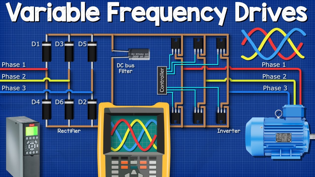
Watch the VFD explanation on YouTube.
Does every overvoltage fault require a braking resistor?
No. Supply conditions, load regeneration, equipment configuration and sensing problems require different investigations. Identify the cause first.
Can I raise the trip threshold to stop nuisance alarms?
Do not change protective thresholds beyond the supplier’s approved configuration. A higher threshold can conceal an unresolved equipment or application problem.
Why does the fault appear only with a loaded machine?
The loaded machine may return more energy or change the operating sequence. Compare loaded and unloaded event records rather than assuming the same braking demand.
Is a longer stop always the final solution?
No. It must still meet machine stopping requirements and pass representative load and repeated-cycle checks.


