




A star delta motor nameplate must permit continuous delta operation at the actual supply voltage, and the motor must expose the winding connections required by the approved starter circuit. Six terminals alone do not prove eligibility. For example, a motor marked 400 V delta / 690 V star may be a candidate for star-delta starting on a 400 V supply; a motor marked 230 V delta / 400 V star is not suitable for that same changeover on 400 V. Voltage compatibility is only the first gate. Starting torque, winding identification, protection and the driven load must also be reviewed before a cabinet is ordered.
Read the voltage symbols with the numbers
Photograph the complete nameplate and the connection diagram. Keep the delta and star symbols next to their associated voltages. Do not transcribe two voltage numbers without the symbols, frequency and current information. A cropped picture or an old maintenance note can omit the detail that changes the selection decision.
In a conventional star-delta arrangement, the starter initially joins the windings in star and subsequently reconnects them in delta for normal running. The final connection therefore has to match the motor’s permitted running voltage. The Engineering Mindset explanation of star-delta starters provides background on those two configurations. Use the installed motor manufacturer’s diagram to establish the actual permitted connections.
Check supply frequency as well as voltage. A motor can have multiple nameplate rows describing different operating conditions. Do not combine the voltage from one row with the power or current from another. When a marking is unclear, obtain the manufacturer’s data for the full motor code instead of inferring a rating from motor size or appearance.
Compare winding voltage in the two connections
For a balanced conventional three-phase winding arrangement, the star winding voltage is the line-to-line voltage divided by the square root of three. In delta, each winding is exposed to the line-to-line voltage. This relationship explains the eligibility check; it does not establish a permissible tolerance, a protection setting or the load’s ability to accelerate.
At an illustrative line-to-line supply of 400 V, the star winding voltage is 400 / √3, approximately 231 V. Delta winding voltage is 400 V. A motor whose winding is intended for 230 V cannot simply be changed from star to delta on that supply. Treat the example as a reading exercise for a conventional nameplate, not as permission to connect unidentified equipment.
The following table assumes a conventional single-speed motor with the stated delta/star voltage pairing and the matching frequency. It is based on the winding relationship above and must be checked against the exact motor documentation. It does not approve a starter, contactor combination or starting duty.
| Nameplate and supply example | Normal running connection indicated | Star-delta eligibility decision |
|---|---|---|
| 230 V delta / 400 V star; 400 V supply | Star | Do not approve changeover to delta on this supply |
| 400 V delta / 690 V star; 400 V supply | Delta | Candidate only; verify winding access, load and starter design |
| 400 V delta / 690 V star; 690 V supply | Star | Do not approve changeover to delta on this supply |
| Symbols, frequency row or winding diagram unreadable | Unresolved | Obtain authoritative motor information before selection |
| Multiple speeds, unusual leads or special winding design | Cannot be inferred from terminal count | Obtain the specific manufacturer’s starting instructions |
Confirm six accessible winding ends
A conventional starter needs access to both ends of each of the three windings so that its contactors can change their connection. The actual lead identification must match the approved drawings. Finding six studs in a terminal box does not prove that the motor is a conventional single-speed design suitable for this method.
Have competent personnel identify the motor and winding arrangement through the manufacturer’s instructions and appropriate de-energized checks. Do not infer winding pairs from where terminals happen to sit. Terminal position, conductor color and another motor’s photograph are insufficient evidence for a new connection.
A motor connected for fixed star or delta operation may have links fitted in its terminal box. An automatically switched arrangement requires the correct separate connections under the starter design. Leaving fixed links in place while adding a changeover circuit can create a serious fault. This article intentionally provides no universal link-position or conductor-color instruction: the motor and starter drawings must agree.
The HSE guidance for work on electrical equipment emphasizes competent work and secure isolation. Apply the site’s approved isolation and verification method before opening terminal boxes or disturbing conductors. A stopped motor or an open control contact is not evidence that its power circuit is safe to touch.
Check whether reduced starting torque suits the load
A correct voltage pairing is necessary, but it cannot establish acceleration performance. Ask the motor and machine suppliers whether the available starting torque is adequate for the actual load and inertia. A machine that starts unloaded can present a different requirement from one that must break away against an existing process load.
Obtain the load description, expected starting condition and permitted acceleration time. Include any unloading arrangement and the consequences if it does not operate. The selection must account for the real sequence, rather than assuming that every pump, fan or compressor behaves like another example from the same category.
If the motor cannot reach the required condition before changeover, increasing a timer is not automatically a remedy. Extended starting can introduce thermal and mechanical constraints. The separate guide on star-delta transition current spikes addresses changeover investigation after eligibility and circuit correctness have been established. Keep the two decisions separate so a wiring or rating problem is not treated as a timing problem.
Review the starter cabinet as a complete combination
For an LNC-QX4 star-delta starter cabinet, submit the motor nameplate and terminal diagram alongside the application data. Ask for the exact selected configuration, power circuit, control sequence, protection arrangement and required motor-cable connections. A cabinet photograph identifies a product example; it does not confirm that the unit has been selected for your motor or supply.
Motor rated current belongs in the RFQ, but a single current value cannot define every component and setting. Contactor duty, overload location, short-circuit protection and the approved circuit arrangement all affect selection. Require the cabinet supplier to identify the applicable documentation and settings rather than applying a generic percentage from an unrelated wiring diagram.
Specify electrical and mechanical interlocking, control supply requirements and the acceptance checks for the assembled starter. Review how the circuit responds to a stop, a protection trip and restoration of power. Those behaviors matter to the installed machine and cannot be inferred from the motor nameplate alone.
Evaluate alternatives when the motor does not qualify
If the nameplate fails the delta-at-supply-voltage test, stop the star-delta selection process. Do not attempt to make it compatible by changing a timer, increasing protection settings or relying on a short test run. Ask the motor supplier whether another approved configuration or a different motor is required.
Other starting methods may be available, but each has its own electrical and application requirements. An autotransformer starter is one possible topic for an engineering review; it is not an automatic replacement recommendation. The following original product photograph illustrates a separate cabinet family, not an internal component or wiring arrangement of the star-delta cabinet.
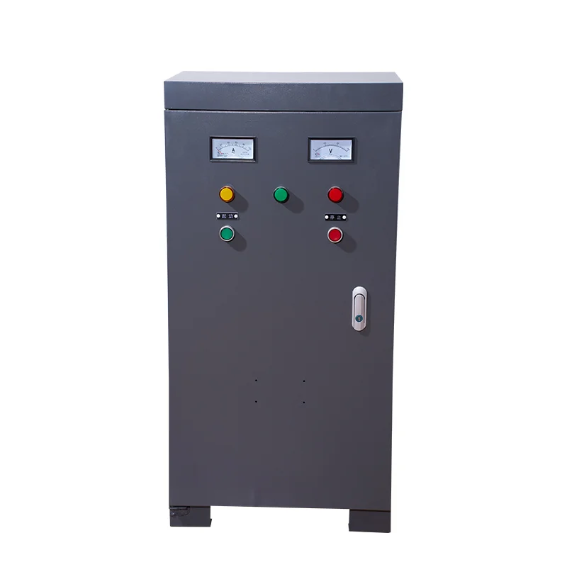
Use the autotransformer starter selection guide to frame that separate discussion about starting current, torque and duty. Provide the same motor and load information so alternatives can be compared against consistent requirements. A different cabinet label does not remove the need to verify voltage and protection compatibility.
Prepare an RFQ package that resolves uncertainty
Provide a legible nameplate photograph, motor manufacturer and full code, rated frequency, normal supply conditions, terminal diagram and the available field-cable arrangement. Include the mechanical load description, intended starts, environmental conditions and any existing protection equipment. State whether the motor is new, reused or recently rewound.
For a reused motor, record known modifications and obtain the current winding information where necessary. An original nameplate may no longer describe a modified machine completely. Treat undocumented repairs as a question to resolve with the responsible motor specialist, rather than assuming the physical plate settles every detail.
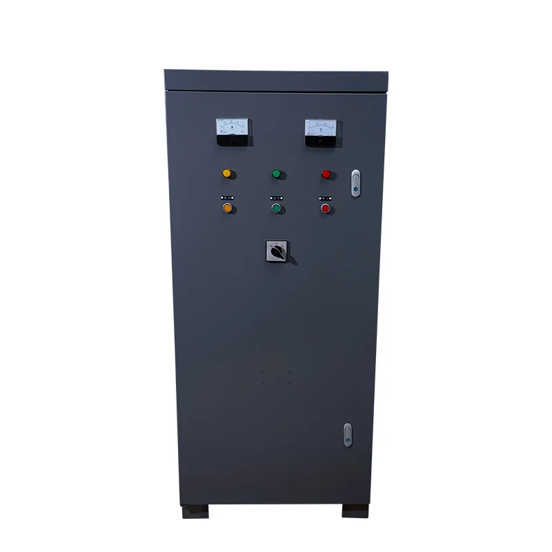
Ask suppliers to list assumptions explicitly. A quotation should identify what is included, what remains subject to verification and which documents will be supplied for installation. For comparison across alternative cabinets, preserve the same duty description and environmental requirements. The next photograph is another original autotransformer cabinet example for that comparison; its enclosure size is not evidence of electrical equivalence or interchangeable ratings.
Verify eligibility before commissioning the sequence
Use a staged acceptance plan. First close the documentary checks: motor identity, voltage pairing, winding access, circuit agreement and component selection. Then perform the approved de-energized inspection and control checks. Energized functional tests come after those gates and must follow the machine-specific method with competent personnel and safeguarding in place.
Record the actual startup condition, transition behavior and steady running result. Compare the observed current, voltage and acceleration with the approved acceptance criteria. A brief successful start is not proof that the motor can tolerate the intended repeated duty or that every fault response is correct.
Maintain a signed handover record identifying the final drawings, parameter or timer values, protection settings and motor data. The star-delta operating-principle guide explains the broader sequence for operators and buyers. Keep that general explanation separate from the installation-specific evidence used to release this machine for service.
Watch the star-delta principle
The Engineering Mindset lesson below shows the principle of changing the winding connection. Use it for conceptual understanding. Connection details and component selection must still come from the approved motor and starter documents, rather than being copied from an educational animation.
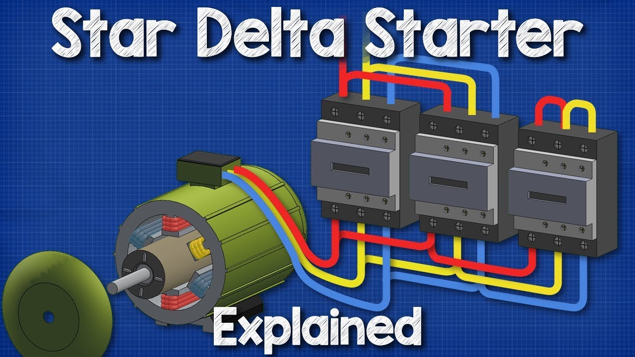
Video by The Engineering Mindset. Watch Star Delta Starter Explained – Working Principle on YouTube.
Frequently asked questions
Is a six-terminal motor always suitable for star-delta starting?
No. Terminal count does not establish the winding design, correct running voltage or adequate starting torque. Confirm the full nameplate, manufacturer’s winding diagram and application requirements before approving a starter.
Can a 230/400 V delta/star motor use star-delta starting on 400 V?
For the conventional pairing described here, it runs in star on a 400 V supply. Changing it to delta would apply the full 400 V across windings intended for about 230 V. Do not approve that arrangement; obtain the manufacturer’s guidance for a suitable alternative.
Does a 400/690 V delta/star marking guarantee a successful start on 400 V?
It can satisfy the normal delta-running voltage requirement, but it does not guarantee acceleration or compatibility with a specific starter. Verify winding access, starting duty, load torque, protection and the approved cabinet circuit before commissioning.


